Related project requirement
Need specifications or pricing for Indoor Wiring Racks?
Share the quantity, drawing or specification and delivery location for a project-specific review.
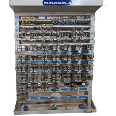
A railway signalling equipment room may contain many relays, terminals, power components and interconnecting wires. Racks provide the mechanical framework that keeps this equipment mounted, identified and accessible. A well-planned rack arrangement supports installation and fault finding; a poorly planned one can make even correctly wired circuits difficult to inspect and maintain.
“Relay rack” is often used as a broad search term, but project documents may distinguish relay racks, cable-termination racks, power-equipment racks and composite racks. The name does not define the supplied configuration. The approved rack layout, equipment schedule and wiring design do.
What a signalling rack contributes
- Secure mounting for the specified relays, terminals and equipment.
- Defined routes for internal wires and incoming or outgoing cables.
- Clear identification of circuits, rows, terminals and equipment positions.
- Working access for inspection, testing, replacement and fault diagnosis.
- A repeatable mechanical interface between equipment and the room layout.
Common rack functions
Relay rack
A relay rack is arranged around the mounting and wiring of signalling relays. Relay type, base, orientation, spacing and access must correspond with the approved signalling design and equipment specification.
Cable-termination rack
A termination rack provides organised interfaces between field cables and internal equipment-room wiring. Terminal type, quantity, segregation, test links, surge-protection provisions and labelling are driven by the cable and circuit schedules.
Composite or combined rack
A composite arrangement combines more than one function within a rack or rack line. It can use room space efficiently, but only when heat, access, segregation, wiring density and future maintenance have been considered together.
Power-equipment rack
Power-related signalling equipment may be mounted separately due to size, heat, electrical segregation or maintenance requirements. The electrical design determines what can share a rack and what must remain separate.
Design the rack from the equipment schedule
Start with the exact equipment list, not a preferred external dimension. Count mounting positions, terminals, spare capacity and cable entries. Confirm equipment depth and the space needed to connect, test and replace each item. Then coordinate the rack footprint with room access, doors, cable trenches, flooring and adjacent racks.
Principal Vinimay supplies indoor wiring racks for railway signalling applications, including project-specific rack categories listed in the catalog. Enquiries should include the applicable rack drawing and equipment schedule.
Wiring access and cable management
Internal routes should protect wires from sharp edges and excessive bending while keeping circuit identification visible. Incoming cables need suitable support so their weight is not transferred to terminals. Wireways, lacing, trunking and separation should follow the approved practice for the installation.
Mechanical and environmental considerations
Rack material, finish, anchoring and rigidity must suit the equipment room and applicable specification. Open frames and enclosed cabinets present different ventilation and access conditions. Seismic, vibration, fire, corrosion or electromagnetic requirements—where specified—must be addressed by the complete design rather than assumed from the rack name.
Maintainability checklist
- Can every replaceable item be reached without removing unrelated equipment?
- Are labels readable in the installed position and consistent with the drawings?
- Is there room for test leads, tools and safe hand access?
- Are cables and wires supported through every transition?
- Can future spare positions be used without rebuilding the active rack?
- Do doors, panels or adjacent racks obstruct equipment removal?
What to send with an enquiry
Provide the rack general-arrangement drawing, equipment and terminal schedule, material and finish, required accessories, room interface details, quantity and documentation requirements. If these are still being developed, identify the design status clearly so the manufacturer can separate assumptions from confirmed requirements.
The practical goal
A signalling rack should make the circuit arrangement easier to understand and maintain throughout its service life. Capacity matters, but clarity, access, identification and mechanical integration are equally important measures of a successful rack design.
Frequently asked questions
What is a railway relay rack?
It is a mechanical framework used to mount and organise signalling relays and associated wiring in an equipment room. Its arrangement follows the approved signalling design.
What is the difference between a relay rack and termination rack?
A relay rack is primarily arranged for relays, while a termination rack organises cable and circuit terminations. A composite rack may combine functions when the approved design permits.
What information is needed to manufacture a signalling rack?
The manufacturer normally needs the approved rack drawing, equipment and terminal schedules, dimensions, material and finish, cable-entry details, accessories, quantity and inspection requirements.
Related railway guides
From research to procurement
Discuss your Indoor Wiring Racks requirement
Send the applicable drawing or specification, quantity, project location and expected schedule. Our team will review the manufacturing and supply scope.
References and further reading
- Relay Rack Design — Railway Signalling Concepts — Railway Signalling Concepts
- Signalling Relays — CG Power and Industrial Solutions
This educational material is a general overview. Project specifications, approved drawings and the latest applicable railway standards govern actual procurement, installation and maintenance.